Black & Decker Screwdriver

Abstract
The goal of this project was to understand the gearbox and the manufacturing of a handheld electric screwdriver. By disassembling the screwdriver I gained a better understanding why it was manufactured the way it was.
Photo credits: Peter Zink, ME359 professor at Boston University.
Gearbox Analysis

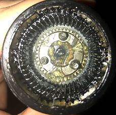
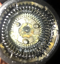
Black & Decker chose to use a multi-stage epicyclic gear train because of the benefits it provides. The gear train is relatively compact, so that it could fit in a small space like the handheld screwdriver. The gear train itself requires only ten parts, but outputs a high gear ratio of 81. Being able to generate a high torque with minimal parts and space was accomplished by utilizing the gear train. The longevity of the gear train also guarantees that the screwdriver will operate for a longer time.
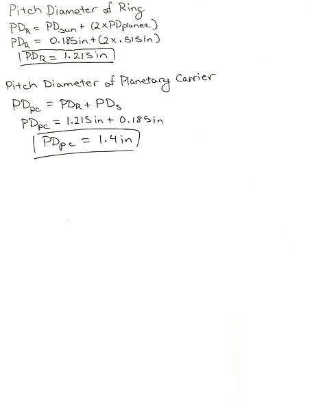


Graphical Representation
Engineering Drawings
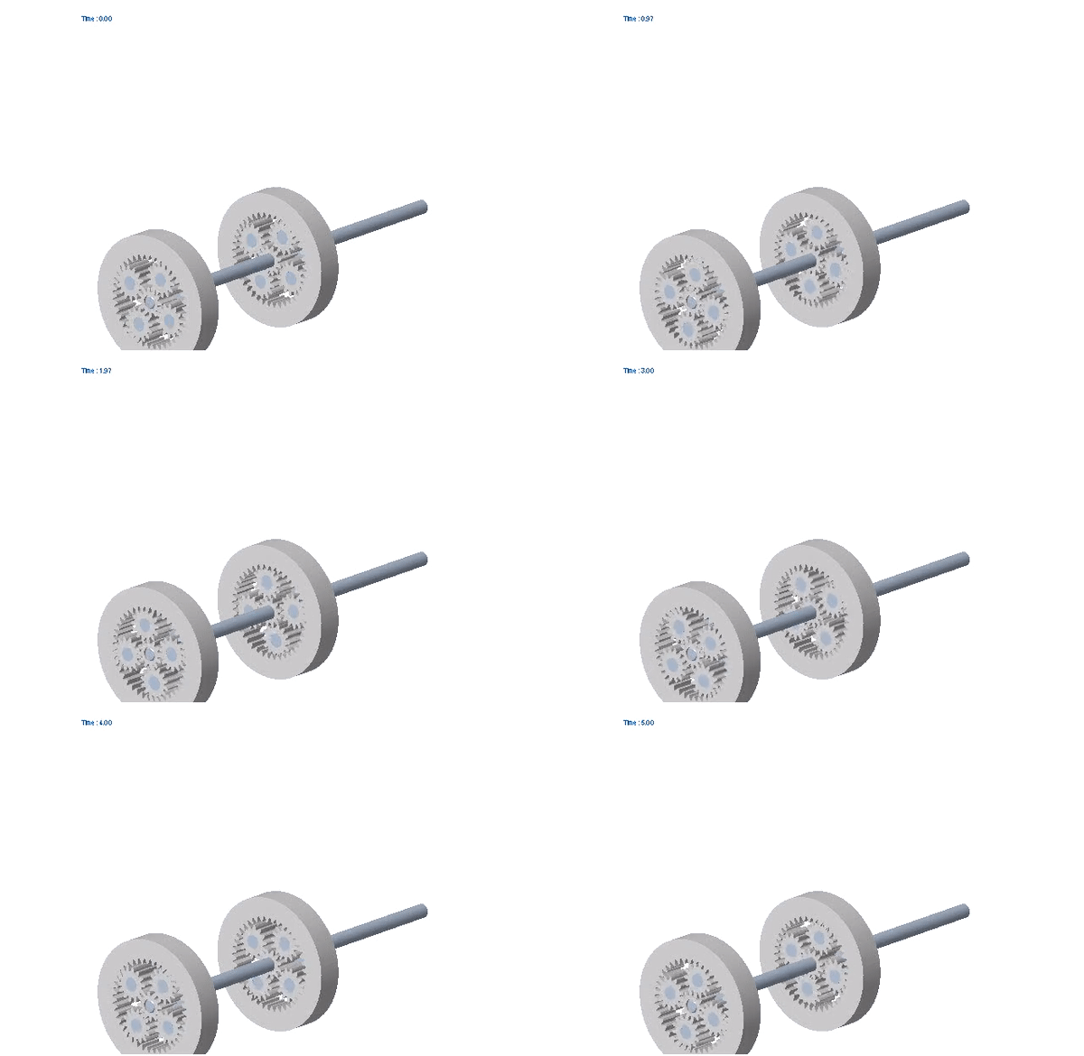
Representation of how the gearbox operates. This is not the exact gearbox used in the screwdriver but it operates in the same manner. The example below is identical in functionality; a multi-stage epicyclic gear train has one sun input and a carrier output.
DMFA: Assembly Mistake Proofing

The plastic casing that holds the screwdriver components in place shows signs of symmetry and specific cuts. The casing was most likely produced through injection molding. This would be one example of replacement done by Black & Decker.
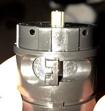

The motor itself can only be attached in one position to the rest of the screwdriver. Unique grooves are cut out in the shell so that the motor only sits securely in once place. Black & Decker had employed the method of prevention.


The output carrier and the sliding power switch can only be assembled in one way. The grooves of the button only fit in one direction, preventing the power switch from being incorrectly installed. This would be another method of prevention.
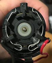
The output carrier connected to the motor has a neutral state manufactured into it. The circuit is open while in the neutral position so that no electricity can flow through from the battery. Two metal prongs are stationary while the carrier can be rotated to touch these prongs and close the circuit. This was implemented to prevent accidentally triggering the screwdriver when not in use. Black & Decker has implemented the method of mitigation for this component.
Mechanical Elements

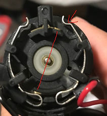

The motor itself is initially disconnected from the power source, leaving an open circuit. Two prongs sticking out from the motor act as the switches in the circuit. The output carrier consists of two semicircular rings connected to the battery. The switch is closed and the circuit is complete when the sliding plastic button is pressed down causing one of the rings to come in contact with the upper prong. Depending on the position of the switch, the motor turns in a specific direction. The motor is able to rotate in two directions due to the change in polarity created by the switch. When the switch is turned right, the rotation goes clockwise. While the switch is turned left, the polarity is swapped because the leading wire is changed. This causes the rotation to go in the counter-clockwise direction.


Handle Pivot Lock
The handle and the rest of the body are connected via a pin joint. Grooves are cut into the joint and the pin itself so that the pin can only fit in a specific position. Both the body and handle are free to rotate about each other while no pin is in it. But the grooves only line up in specific positions. Those positions correlate to the three locking positions available for this model. When the pin is pushed in all the way, the grooves thread together so the whole handle moves. But at the three locking positions, the orange casing's grooves do not line up with the rest of the pin, causing the handle to lock.


Manual/Auto
The manual/auto setting of the screwdriver is controlled at the tip of the device. While the setting is on auto, the second planetary carrier is free to rotate about the ring gear. But when the tip is rotated towards manual, a plastic piece rotates onto the planetary gear, wrapping around its teeth. This stops the planetary gear from outputting rotation into the chuck.


Conclusion
Takeaway: I think the most interesting thing I learned from doing this deconstruction project was the amount of thought put into manufacturing this device. This electric screwdriver is relatively compact and simple compared to a power drill. As a consumer, I initially did not think about how much work was put into creating this device. After disassembling the screwdriver it was obvious that the manufacturer put immense effort into it. From ease of assembly to user safety, Black & Decker incorporated numerous manufacturing principles. I'm astound by the amount of thought required to create anything.
After taking apart this device, analyzing it and putting it back together, this project was a learning experience. For example, a real world application of gear train analysis was used to understand why B&D decided to use an epicyclic gear train. Taking apart the screwdriver provided insight to the DFMA principles used in a real life product. Anyone can takeaway that a simple product has great complexity behind it.


