2.5 DOF Motion System
This specific project was originally meant to be a physical product created in person, but due to unforeseen circumstances, it was switched over to strictly a computer simulation created in SOLIDWORKS. Nonetheless, the ideas and application behind it were the same. This project allowed for exposure using SOLIDWORKS via designing, assembling, and motion simulation. The task at hand creates an opportunity to practice mocking up virtual prototypes, that is often important in the design process in manufacturing and industry.
A 2.5 axis system was created with a 2 DOF placement sub-system and an actuator device. As a team, we chose to simulate a crane system due to its functionality and importance in real life.

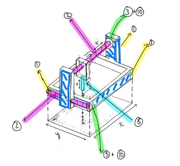
Original Sketch Idealized
Design & Thought Process
With 8020 Aluminum T Extrusions available as parts, we thought to make a frame for the crane in the form of a cube. Along the frame there would be three lead screws mounted so that movement could be achieved in the x and y directions. Two lead screws would be mounted parallel to each other with motors driving each side to to provide movement in the y-axis and prevent torque from happening on either side. The crane would be placed on the x-axis, mounted to only one lead screw allowing for full movement across the platform.
The actuator would consist of a linear actuator as well as a claw with rotary functions. This would allow for the crane to extend and retract for different sized objects, as well rotate for different orientations if needed.
The creation of the system would allow us to practice skills such as: ideation, teamwork, joining & assembling, employing electro-mechanical components, and mechanism simulation.
Results

The finished product utilizes the ideas that we set out for in the beginning. The system itself consists of multiple subsystems working together.
Motion studies in SOLIDWORKS allowd for a virtual demonstration of how the system would act in real life.
Demonstration of all moving compenents in sync
Crane Grabber

The motor starts the gear train which begins with two spur gears.
The second spur gear connects with a shaft that has a worm gear attached at the bottom of it. The worm gear rotates two more spur gears.
The left and right spur gears are connected to arm pieces that are free to move.

Frame & Carraiges

Frame consists of 24" x 24" aluminum extrusions, three servo motors and three lead screws.
.png)

The y-axis carriages consist of a rectangular box with a wheel support that moves along the grooves in the frame while being driven by the lead screw. The x-axis carriage holds the linear actuator and a support rod for stability and prevents swinging while translating across the plane.
Evaluation
The end product met our team's expectations. We learned much about mechanical simulations and diversified our skills through SOLIDWORKS. Some improvements we thought about for the future of this design include: (1) adding interchangeable claws/grips, (2) more compact carriages, and (3) an improved guide rail system.


