Linear Motion Sequence 2- Closed Loop Control
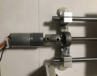
This design project serves as a follow-up to Design Project No. 1. Utilizing the same linear stage, a DC gear motor is implemented in place of the stepper motor. The goal of this project is the same as before, to create an automated system capable of moving a carriage to a predefined location along a linear path. Specifically a 1lb rigid load will be applied to a 5"x5" platform without affecting the linear motion. A closed loop control is used to control the motion sequence. For more information regarding the design of the linear stage, refer back to Design Project No. 1.
DC Gear Motor
A gear motor utilizes a gearbox with a motor in order to create a high torque output at low speeds. These motors are suitable for tasks requiring more force with high efficiency.

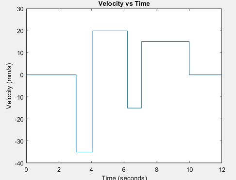
The linear motion sequence begins by triggering the switch. The stage will home towards the trigger at 35mm/s after a 1 second delay. Once the switch has been triggered, the stage will move away 10mm at 20mm/s. After it has finished, it will home back once again at the lowest possible speed that can be outputted by the gear motor. At last the switch will be triggered once again, sending the stage away 30mm at 10mm/s. The process then come to an end.
Linear Sequence in Motion Demonstration
Principles
In order to fully under the controls of the gear motor, several relationships have to be explored and defined. Through trial and error, the gear motor rotation is defined as 374 pulses per revolution. Incorporating lead of the screw can determine the distance traveled per pulse. The 8mm lead screw moves 8mm per revolution. Combining both relationships, the distance traveled on the lead screw becomes 0.02139mm per pulse. The voltage fed into the motor is interpreted through a range of 0 - 255 based on the bits available in the Arduino. The input voltage has a direct relationship with the velocity. When the power is adjusted the velocity of the motor changes with it. The time it takes for a distance to be traveled can be found by dividing the distance by velocity. The voltages needed for the specified velocities were experimentally determined through trial and error.
Pins 12, 3, and 9 are defined as the direction, voltage, and break respectively for coil A. Pin 7 is defined as the encoder for B. Pin 10 is used as a pullup switch input in order to automatically change the motion sequences. Each motion sequence is either triggered while the switch is high or low. When pin 12 is high, the motion of the motor is counterclockwise, and when it is low the motion is clockwise. The analog write function programs the voltage received by the motor, which varies depending on what the desired output speed is. The motion duration of the motor is defined by its delay. The following delay is the time that it takes for the carriage to travel a predefined distance based on a specific velocity. Time and pulses are measured from the beginning of the program in order to trace the motion as a function of time. The pulse can be used to be converted into displacement and speed to be graphically displayed as a function of time.
Linear Motion Sequence Arduino Code


Electrical Diagram


