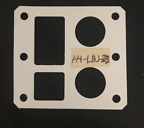
Gasket Project

Front View

Back View
The purpose of this assignment was to create a gasket that would fit onto an aluminum block that was given without obstructing any of the surface features. The underlying meaning behind this assignment was to immerse and improve skills in metrology, sketching, using CAD software, using CAM software, and using a CNC mill.
The task at hand required the need to take measurements of the original aluminum block using calipers, creating a sketch based off what was measured, create a CAD model based of the sketch, and import the CAD model into GibbsCAM to create a final product using a CNC mill.

The first thing done was measuring the outer dimensions of the block. Afterwards, the features inside the block were measured. The rectangular cutouts had their dimensions driven relative from their positions to an outside edge. The circular cutouts had their diameters measured, and the position from the center to the edges measured. The same technique for the circles were applied to the six smaller holes. Once all the measurements and positions of the features were noted, a CAD model was easily produced.
The CAD model was easily created using the sketch as a guideline. After importing the CAD model into GibbsCAM, the CAM program was used to create a G-Code that would drive a CNC to produce the model. The final result was a manufactured gasket that closely resembles the original aluminum block.

The final product fit on the gasket with a few minor issues. As a result of poor measurement, the rectangular cut outs were shifted downwards by a hundredth of an inch. As can be seen below, the gasket cut out for the rectangles do not perfectly align. The reason behind this was that while taking initial measurements for the position of the upper rectangle, the dimensions were incorrect. The initial measurement between the top edge and top edge of the rectangle was 0.25", but after measuring it again the distance was actually 0.22". Since the dimension was off by 0.03", the entire cutout was shifted downwards by that amount. The distance between the bottom rectangle's edge and the bottom edge of the gasket turned out to be 0.21" instead of the initial measurement of 0.19". These mistakes could have been avoided by being more careful while taking measurements as well as taking measurements multiple times to get an accurate value. One general takeaway from the mistakes made is to take time and be extra careful while taking measurements because how crucial the information is when manufacturing on a large scale.


